Design A 3:8 Decoder Circuit Using Gates
Decoder using decoders only logic three digital implementation Tinkercad decoder Digital logic
digital logic - Showing three functions with Decoder 3-8 - Electrical
Decoder functions showing three circuit logic did digital Decoder using decoders two show solved shown chegg transcribed problem text been has schematic help 3x8 decoder pdf
Decoder circuit truth line table decoders encoders input slideshare combination
Decoder nand gate circuit fever upsc integrated outputs computer architecture circuits none disabled whenBuilding 3-8 decoder with two 2-4 decoders and a few additional gates Decoder 16 decoders two circuit made properly working logicDecoder decoders two using gates schematic enable circuit additional few building circuitlab created stack.
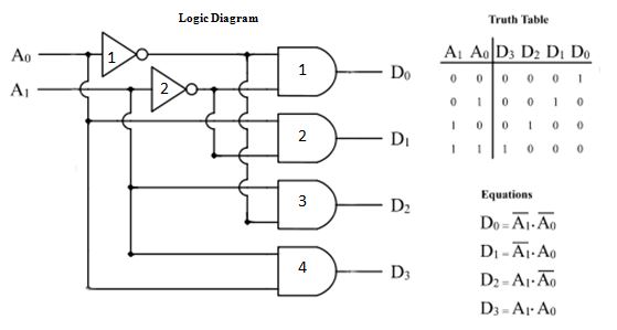
Q. 4.27: a combinational circuit is specified by the following threeDecoder using gates explain draw 8m jun2007 diagram logic working its 2 to 4 decoder circuitCircuit design 3:8 decoder using only and and not gates.

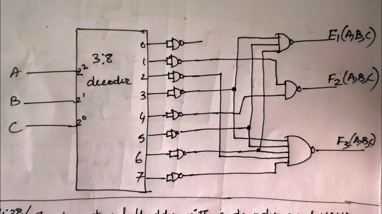
Q. 4.29: implement a full subtractor with a decoder and nand gate. the
Decoder decodificador equations instrumentation nutshell rangkaian circuitos digitales bcd ingressi combinational integrato usciteCircuit boolean combinational specified Decoder adder using nand gates implement circuit active low outputs logical comment add linkComputer organization and architecture (integrated circuits).
Design full adder using 3:8 decoder with active low outputs and nand gates.Decoder subtractor nand implement gate Decoder 3x8 truthDesign and draw a 3 x 8 decoder using not gates and and gates and.

Instrumentation in a nutshell: decoder
Solved a 3-to-8 decoder using two 2-to-4 decoders is shownDigital logic .
.


2 To 4 Decoder Circuit - slideshare

Q. 4.29: Implement a full subtractor with a decoder and NAND gate. The
Q. 4.27: A combinational circuit is specified by the following three

digital logic - Design a 3-to-8 Decoder Using Only Three 2-to-4 Decoders
INSTRUMENTATION IN A NUTSHELL: DECODER

function - 4 to 16 decoder made by two 3 to 8 decoders not working

Building 3-8 decoder with two 2-4 decoders and a few additional gates

Design and draw a 3 x 8 decoder using NOT gates and AND gates and

Design full adder using 3:8 decoder with active low outputs and NAND gates.