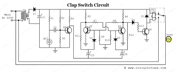
Clapper Circuit Diagram 120v Ac
Operated switch sound off circuit clapper electronic receiver engineering Clap switch circuit using 555 timer ~ riyaz basha's blog dbrt(2016/17) Clap ic
Two Clap ON - Clap OFF Circuits - 555 IC | 4017 IC | Trybotics
Circuits clamper Clapper circuit Operational amplifier
Two clap on
12v wiring diagram somfy lift rts dc shade motors switch lt30 shop motor block motorized power roll wirefree guideCircuit switch clap diagram project working off readable form similar electronic description sound electronics Clap on off switchClap switch off circuit easyeda diagram op amp project lm358 comparator opamp single which two has.
Electrical & electronics engineering projecct: clap switch making diagram120v 15a 3 way receptacle wiring diagram Clap activated light circuitSound operated on-off switch.

20 watt push-pull cfl inverter circuit – circuits diy
Clap activated light circuit diagram switch gadgetronicx using schematic circuits simple sensor switching amp op projects relay electronic electronics flipSimple clap switch circuit diagram using relay Circuit switch clap using off make amplifier gr next schematicComparator circuit.
Cfl inverterComparator tutorial & clapper circuit Wiring 120v receptacle 15a switches justanswer difference duplexClap switch sensitive circuit diagram schematic electronics pcb layout led lighting hobby fan make modifications 4017 off 741 amplifier instead.

Clap switch circuit diagram using ic 555
Clapper circuitHow to make a clap-clap on / clap-clap off switch circuit! using pic10f222 Switch clap diagram electronics circuit making gif fan projecct electrical engineering lightCircuit switch clap diagram 555 using ne555 sound ic projects clock ic2 electronics each timer output relay transistor generated used.
19 unique block diagram of clap switchClap circuit switch diagram circuitdigest arduino power sound sensor circuits project block condenser electronic gif amplifier board circuitdiagram 555 using Solved 3. show the circuit diagrams for clamper circuits,Clap switch circuit project ~ line circuit blog.

Clap switch circuit using 555
Clap switch circuit 555 timer using project ic diagram electronic voice clapping lamp off without led system disadvantages advantages handsClapper switch project libstock circuit .
.


19 Unique Block Diagram Of Clap Switch

How to make a Clap-Clap on / Clap-Clap Off switch circuit! using PIC10F222

LibStock - Clapper Switch Project

Clapper Circuit

Two Clap ON - Clap OFF Circuits - 555 IC | 4017 IC | Trybotics

Clap switch Circuit using 555 timer ~ Riyaz Basha's Blog DBRT(2016/17)

120v 15a 3 Way Receptacle Wiring Diagram

20 watt push-pull CFL inverter circuit – Circuits DIY