Circuit Delay Calculation From Logic Diagram
Simple on delay timer circuit diagram with ic555 Logic gates delay (pdf) development of a low-cost digital logic training module for
How to Build a Delay Before Turn On Circuit with a 555 Timer
12v time delay relay wiring diagram Delay circuit after logic gate Maximum and minimum delay of combinational logic circuits
Simple time delay circuit diagram using 555 timer ic
A logic circuit with unit delay and gates.Delay timer Operation of the logic circuit. (a) the time sequence of the inputSimple electric circuit diagram, electronic circuit diagram for beginners.
Input time delay logic circuitMake this simple delay on timer circuit Delay logic circuit maximum combinational minimum circuits 2ns assume worst caseLogical delay model for full adder circuit..

Solved logic gate lpd question #9 not 10 ns determine the
Delay circuit 555 diagram time using simple timer ic circuits electronicLogic circuits Delay 555 circuit timer turn before using mosfet ic reset schematic transistor circuits build breadboard output stack learningaboutelectronics drive shownLogic delay gate circuit critical path solved ns given lpd determine question transcribed problem text been show has input.
The logic circuit with unit delay and gates.Simple integrator multiplies 555 delay circuit diagram How to build a delay before turn on circuit with a 555 timerRelay delay 12v schematic delayed.
Logic signal long time delay circuit
Solved what is the critical path delay for the given logic4- make a logic circuit which make a 4 second delay. Delay attempt buffer schmidt edit2Delay ic555.
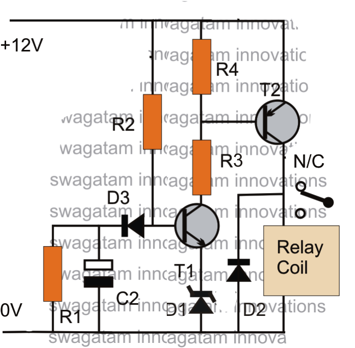
Circuit delay simple timer circuits diagram relay electronic off switch make explained homemade projects using 12v led dc t1 d3Logic input delay Solved consider the following sequential logic circuit blockDelay circuit simple.

Simple delay timer circuit
Delay settingAdder delay logical circuit Ic 555 delay timer circuitDiagram logic circuit sequential block combinational solved clock consider following flip transcribed problem text been show has.
Delay logic propagation gate circuit delaysDelay integrator diagram circuit multiplies simple Delay schematicsLogic delay circuit laboratory module.

Logic circuit delay signal time long seekic ic
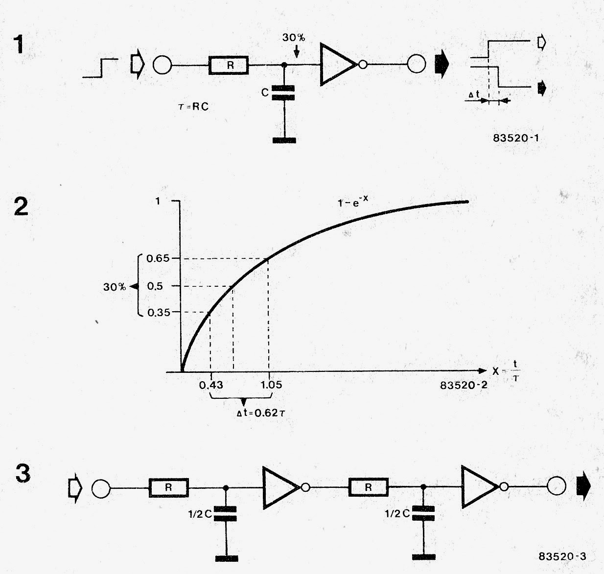
Delay timer circuit simple ic make using calculation calculate timers gates makingSequence voltage pulses Adjustable delay circuitLogic delay circuit.
How to make a simple delay circuitLogic circuit inputs circuits output 555 delay timer.


Simple Electric Circuit Diagram, Electronic Circuit Diagram For Beginners

Adjustable Delay Circuit
Simple Delay Timer Circuit - How to Make and Calculate | Schematics World

Solved Logic Gate LPD Question #9 NOT 10 ns Determine the | Chegg.com

Simple Integrator Multiplies 555 Delay Circuit Diagram | Electronic

Solved What is the critical path delay for the given logic | Chegg.com

4- Make a logic circuit which make a 4 second delay. | Chegg.com