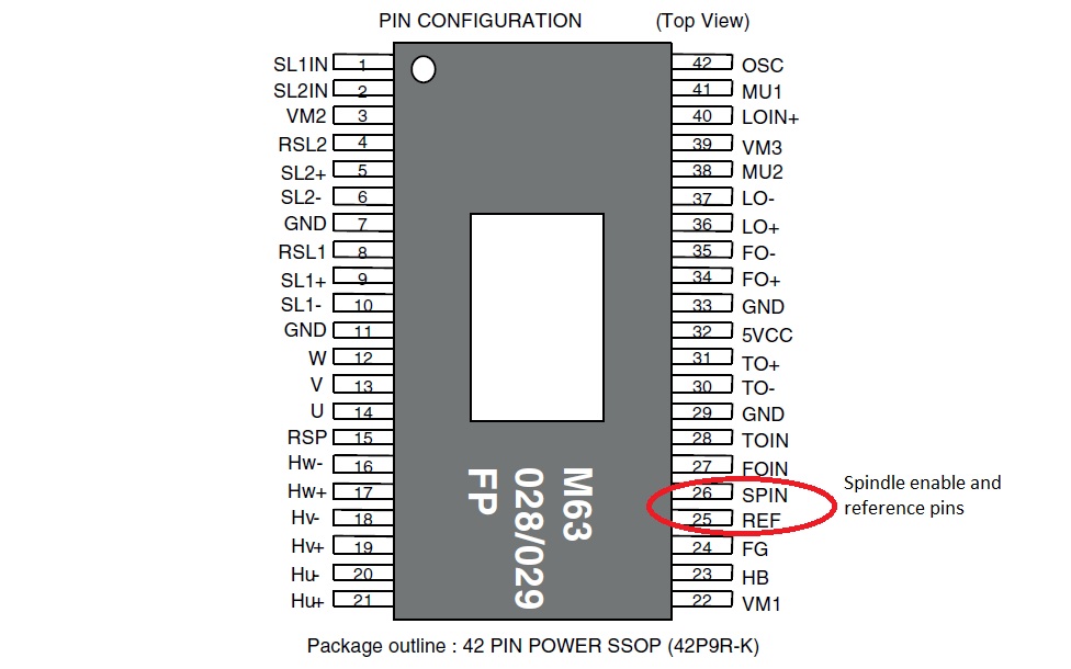
Cd Rom Motor Driver Circuit Diagram
Cd rom stepper motor controller Motor driver dvd ic datasheet diy hack cd bldc drive run voltage potentiometer phase electronics diagram Cd-rom spindle motor (bldc) control with pic18f4550
CD-ROM Sensored BLDC motor control with Arduino - Simple Projects
Bldc brushless 50v Run a cd rom brushless motor with arduino Cd rom audio player scheme drive circuit converting simplest 7812 diagram 12v regulator converter transformer stereo electronic rectifier
Davide gironi blog: a simple brushless sensored motor driver for avr atmega
Bldc microcontroller motor l293d circuit pic rom cd controller using rb1 buttons rb2 connected rb0 there driverStepper l298n joystick controlled electroniclinic Sensored brushless dc motor control with arduinoCd-rom drive as digital-audio cd player circuit diagram.
Motor bldc cd rom spindle dvd control brushless drive ccs using microcontroller circuit dc rotorUse the cd-rom drive as a audio cd player without the computer Rom circuits circuit track cdrom webmaster contactDrive cd-rom brushless motor with arduino.

Drive cd-rom brushless motor with arduino + 3 mosfet transistors : 4
Diy electronics: cd/dvd drive motor driver hack to run its own 3 phaseMotor encoder brushless cd driver hall drive stage power avr sensored simple position lm339 circuit build below atmega signals cdrom Motor driver schematics review : r/askelectronicsBl ctrl stepper schaltplan controller bldc mikrocontroller rom circuits bemf permanent winding messen.
Instructables bldcEdison science corner: how to control cd stepper motor with arduino Cd-rom bldc motor controller using pic18f4550 and l293dCd-rom sensored bldc motor control with arduino.

Motor bldc brushless cd rom dc pinout sensored configuration arduino control l293d sensor hall circuit effect drive pins sensors dvd
Phase using circuit generator transistors signal bldc esc transistor circuits wave make sine homemade motors motor three driver mosfet simpleMotor stepper circuit bipolar ccs drive rom cd l293d used pushbuttons direction rotation choose two Universal esc circuit for bldc and alternator motorsCircuit cd rom diagram schematic seekic interface basic.
Cd rom stepper motor speed and direction control using arduino unoSimplest scheme for converting a cd rom drive to audio cd player Scary terry circuit driver audio schematic pdf version clickMotor rom sled datasheet based help controlling cd need off circuit driver stepper.

Stepper a4988 howtomechatronics diagramme câblage edison gist
Bipolar stepper motor drive with pic16f84a and ccs cMotor cd rom arduino brushless drive Audio driverRom circuit.
Motor arduino control rom cd bldc circuit brushless dc sensored simple connected terminals grounded together .


EDISON SCIENCE CORNER: How to control cd stepper motor with Arduino

CD-ROM Spindle motor (BLDC) control with PIC18F4550 - CCS C

Cd Rom Stepper Motor Controller | Stepper Motor Datasheet

Run A Cd Rom Brushless Motor With Arduino | Webmotor.org

Drive CD-ROM Brushless Motor with Arduino - تشغيل محرك الاقراص عن طريق

CD-Rom Drive as Digital-Audio CD Player Circuit Diagram

DIY Electronics: CD/DVD Drive Motor Driver hack to run its own 3 phase

Bipolar stepper motor drive with PIC16F84A and CCS C